


The Mossberg Model 500: History & Disassembly
First designed and marketed in 1962, Mossberg’s Model 500 pump-action shotgun is a popular arm, due no doubt to its well-balanced combination of affordability and quality. The “modular” nature of the Model 500 product line certainly doesn’t hurt either, and a dizzying number of barrel and stock options allow users to make a single Model 500 into either a pistol-gripped cruiser model or a 28″-barreled bird gun by simply switching out a few parts.
The Mossberg 500 utilizes an aluminum receiver to reduce weight. Housed inside the Model 500’s bolt is a steel bolt lock that engages a recess in its steel barrel extension for steel-on-steel lock up.
Barrels are interchangeable within specific gauges and have been produced with and without ventilated ribs; open sights, bead sights and integral scope bases; in lengths from 18 1⁄2″ to 32″; C-Lect-Chokes and provision for screw-in Accu-Chokes; smooth or rifled bores and even in a .50-cal. rifled muzzleloading version. Stocks and fore-ends, originally of plain walnut, are also found made of checkered birch or synthetics—some finished black, some with camouflage patterns. Buttstocks with interchangeable combs or with shell holders for quick reloading have been available, as have fore-ends with built-in laser sights.
- Buy All-American!
- Bring health and vitality back to your body with these non-transdermal patches
- Get your Vitamin B17 & Get 10% Off With Promo Code TIM
- How To Protect Yourself From 5G, EMF & RF Radiation - Use promo code TIM to save $$$
- The Very Best All-American Made Supplements On The Market
- Grab This Bucket Of Heirloom Seeds & Save with Promo Code TIM
- Here’s A Way You Can Stockpile Food For The Future
- Stockpile Your Ammo & Save $15 On Your First Order
- Preparing Also Means Detoxifying – Here’s One Simple Way To Detoxify
- The Very Best Chlorine Dioxide
- All-American, US Prime, High Choice Grass-Fed Beef with NO mRNA, hormones or antibiotics... ever!
The Model 500 owes a good share of its popularity to its military and police service. First utilized in 1979 by all major branches of the U.S. Armed Forces in it’s Model 500 guise, requests for increased ammunition capacity and other modifications resulted in the Model 590 shotgun (a variant of the Model 500) that was adopted in 1987. This accounts for standard gun add-ons such as sling swivels, barrel heat shields and pistol grip sets that are not shown on the accompanying “Exploded View.” It represents only the basic gun, the heart of what the factory calls “The Mossberg Shooting System.”
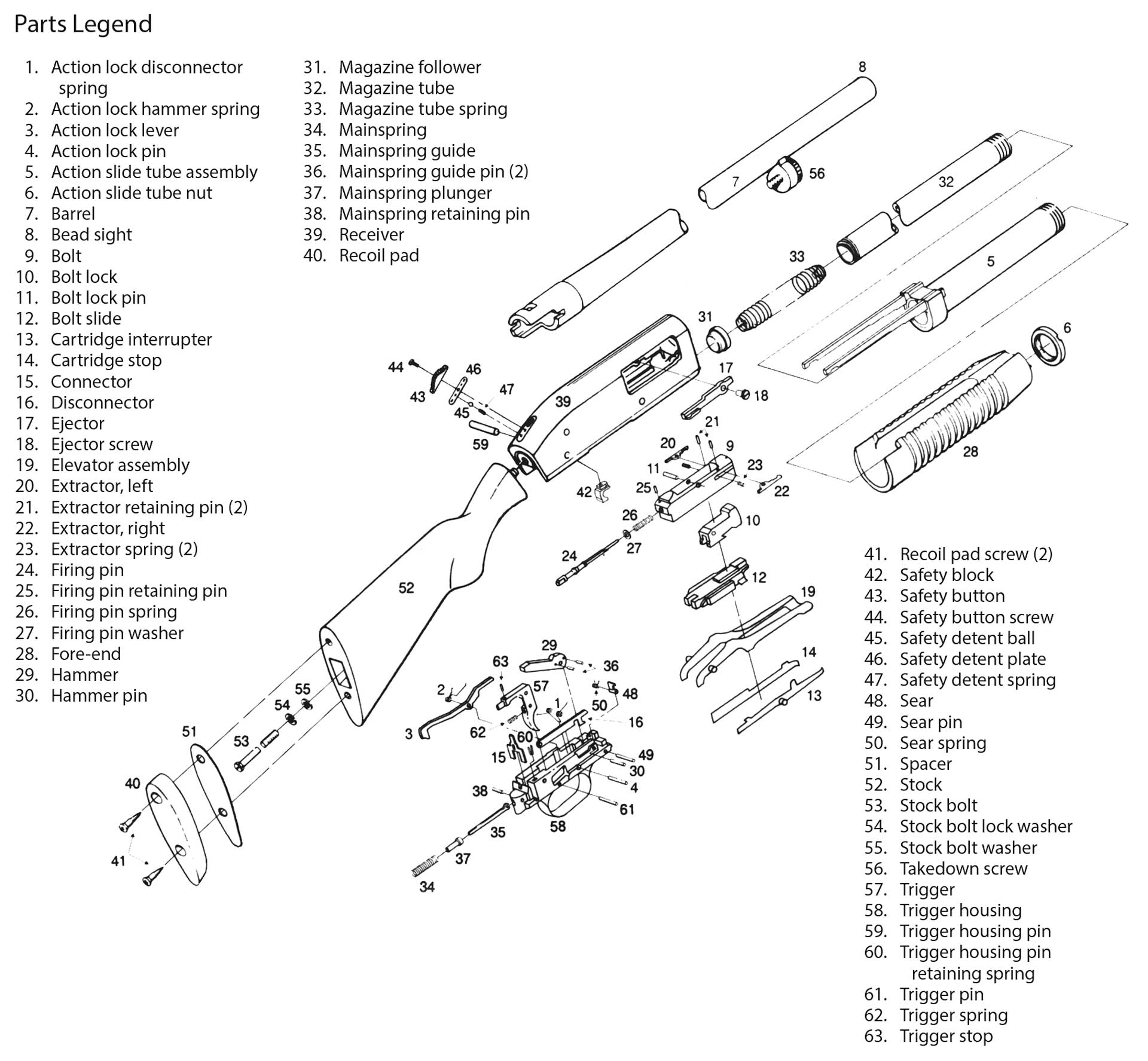
Disassembly
Begin by depressing the action lock lever (3) located behind and to the left of the trigger housing (58).
Retract the fore-end (28) to open the action and check the chamber, elevator (19) and magazine tube (32) to make sure the gun is unloaded. Slide the safety button (43) rearward to the “on” position.
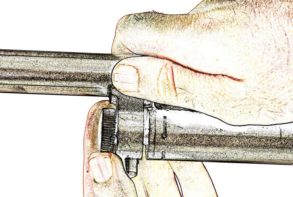
Move the fore-end forward until the front of the bolt (9) is centered in the ejection port opening, then turn the takedown screw (56) at the front of the magazine tube (Fig.1) counter-clockwise until the threads are no longer engaged. The barrel (7) can now be removed by pulling it forward.
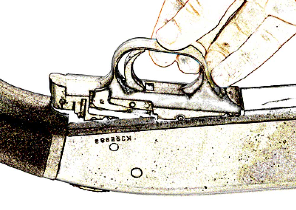
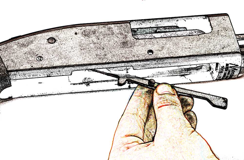
Next, place the gun on a flat surface with the trigger housing facing up and drive out the trigger housing pin (59) from left to right. The trigger housing is removed by pulling upward at the back (Fig. 2), then out and free of the receiver (39). Make sure the trigger (57) is not pulled during removal. Further disassembly of the trigger assembly is not recommended by the factory and should not be required for routine cleaning and maintenance.
Remove the cartridge interrupter (13) and cartridge stop (14) (Fig. 3) through the opening in the bottom of the receiver.
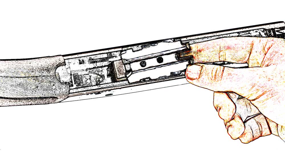
It may be necessary to tap lightly on the sides of the receiver with a wooden or plastic mallet to free those parts. Slide the fore-end three-quarters of the way rearward, until the bottom of the bolt slide (12) lines up with the clearance cuts in the side of the receiver. The bolt slide is now lifted up and out of the receiver (Fig. 4).
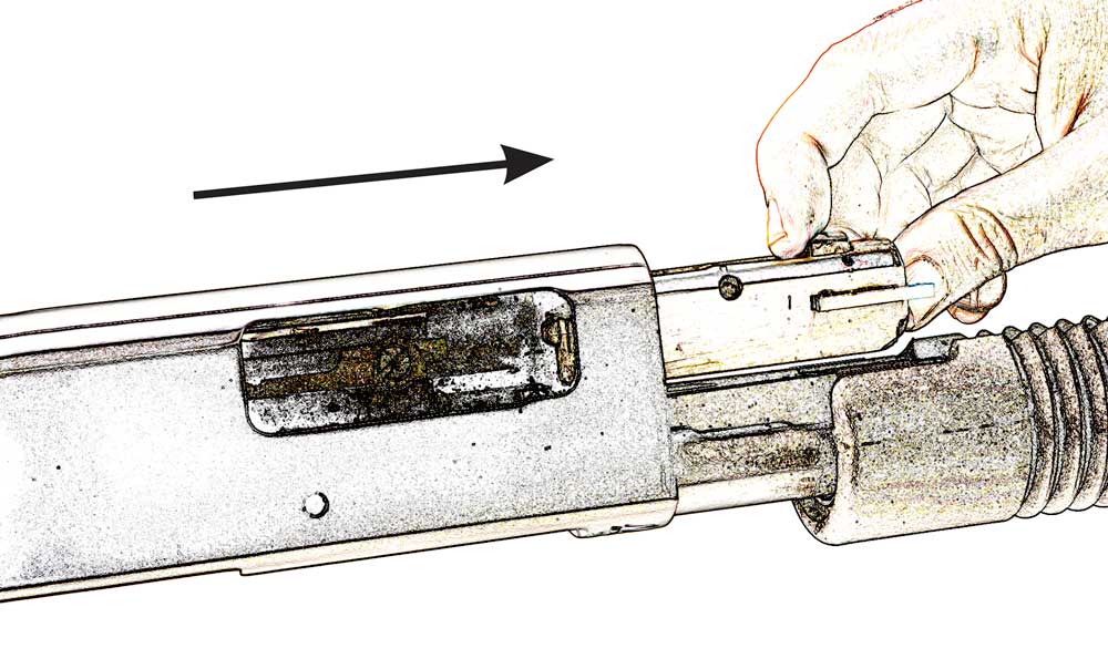
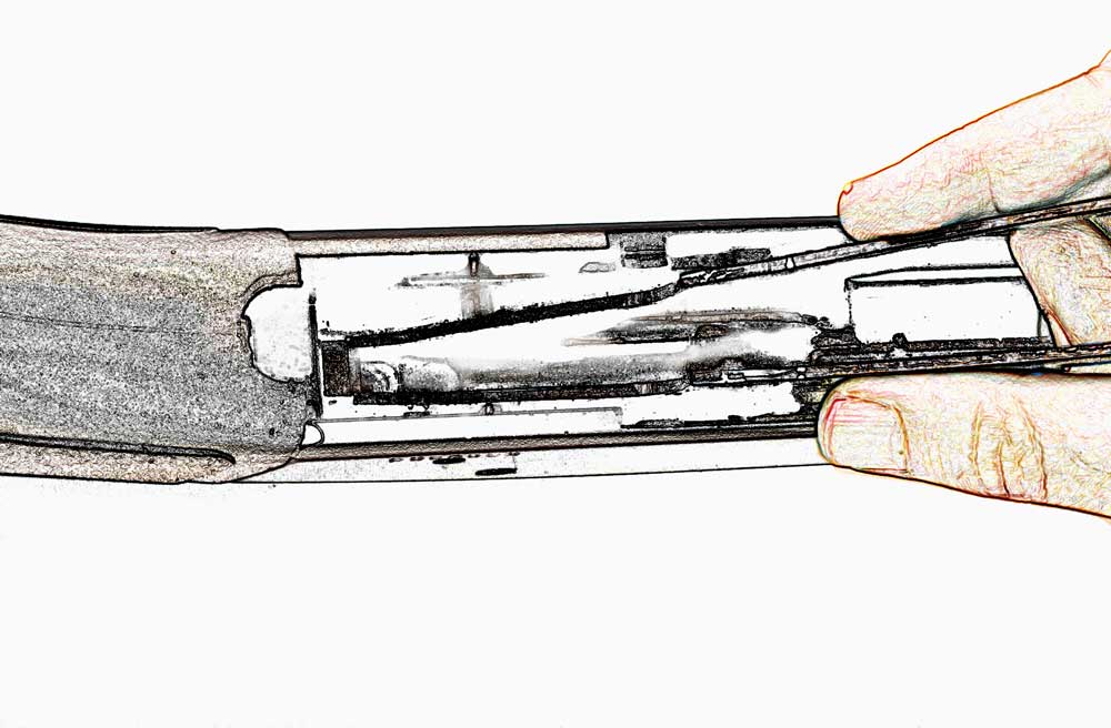
Next, the bolt assembly is slid forward through the opening in front for the barrel assembly and out of the receiver (Fig. 5). The factory does not recommend further disassembly of the bolt.
Ensure the safety is in the rearward or “on” position before attempting to remove the elevator assembly. Lift the forward portion upward, and apply pressure on both sides of the elevator arms (Fig. 6) until the pins no longer contact the sides. Lift the elevator out through the bottom of the receiver.
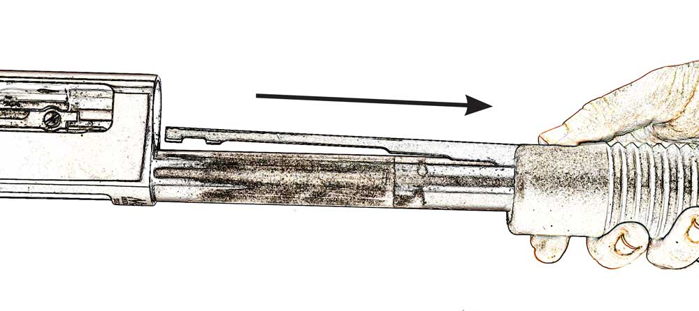
The action slide tube assembly (5) is now removed by slipping it forward and free of the magazine tube (Fig. 7).
Insert a screwdriver of the proper size through the ejection port and turn out the ejector screw (18), then withdraw the ejector (17).
If it is necessary to remove the stock (52), loosen the upper recoil pad screw (41) and turn out the bottom one. The recoil pad (40) and spacer (51) are rotated sideways to allow access to the stock bolt (53). Turn out the stock bolt and remove it from its well. The stock is now pulled off the receiver to the rear.
Reassembly is in reverse order. Be aware that the hammer must be in the full-cock position for reinsertion of the trigger assembly and that the safety must be in the “on” position to re-install the bolt assembly.
Article by MICHAEL O. HUMPHRIES


